ESP32 IoT API – Dual-Channel Graph Plot & RMS Meter
Build a self-hosted IoT measurement node: the ESP32 continuously computes true RMS and Graph Plot on two analog channels and exposes the latest values through a clean HTTP JSON API for scripts, dashboards, and automation.
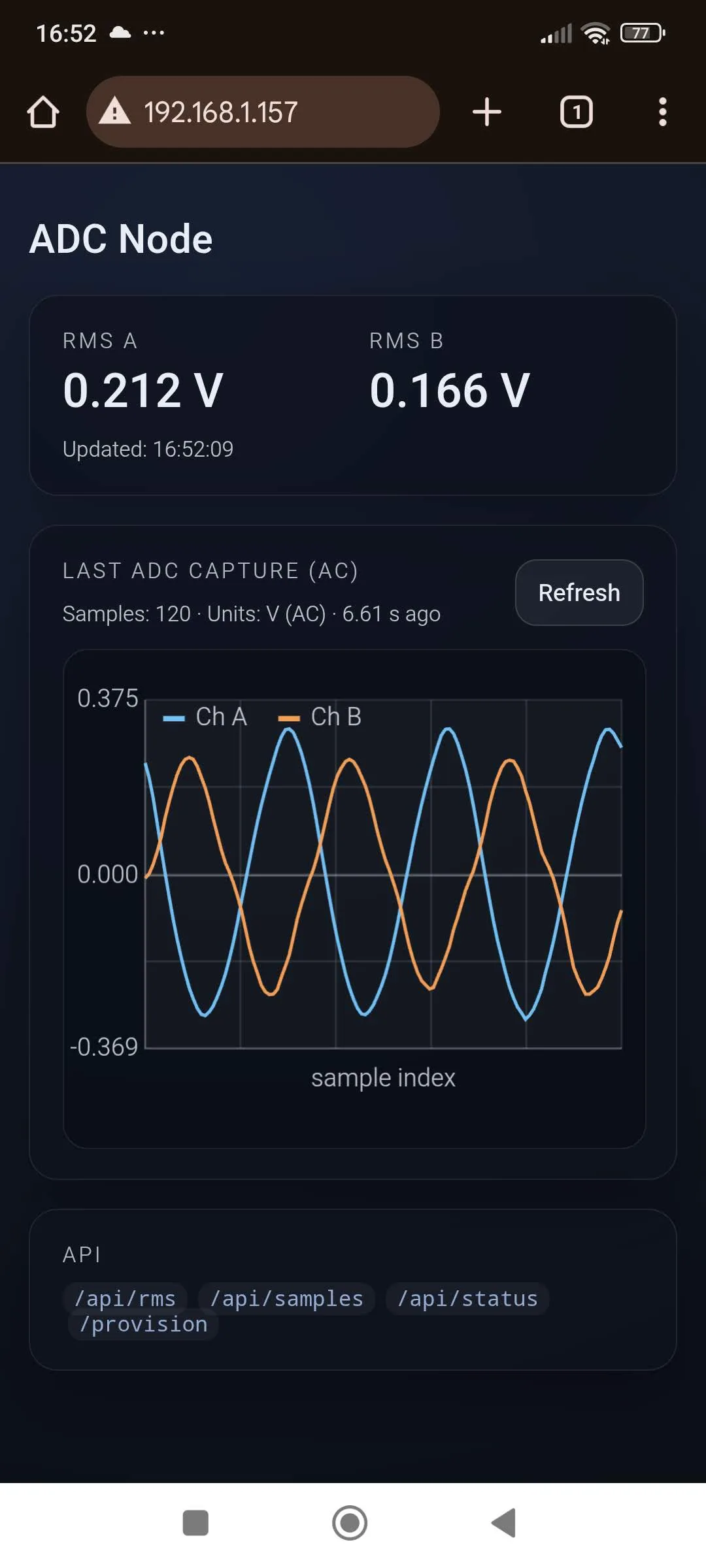
Once connected to Wi-Fi: the ESP32 exposes the latest RMS and Graph Plot measurements via a local HTTP JSON endpoint, accessible from any device on the same network.
curl http://<ESP32_IP>/api/rms{
"channel_a_rms": 0.212,
"channel_b_rms": 0.106,
"unit": "volts",
"timestamp_ms": 41596000
}IoT, RMS Measurement API (Dual ADC) & Graph Plot
Connect the ESP32 to your home Wi-Fi network.
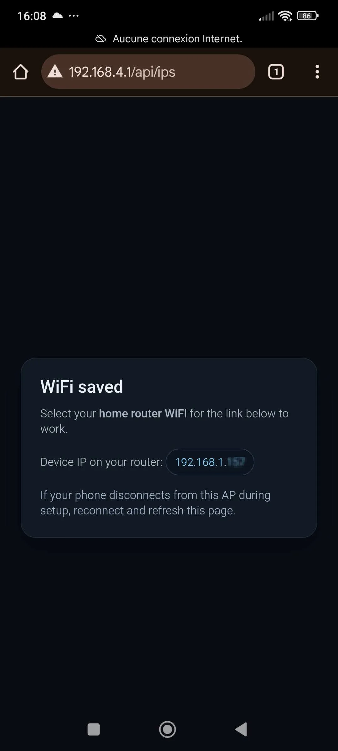
Obtain the IP address assigned to the ESP32 by your home Wi-Fi network.
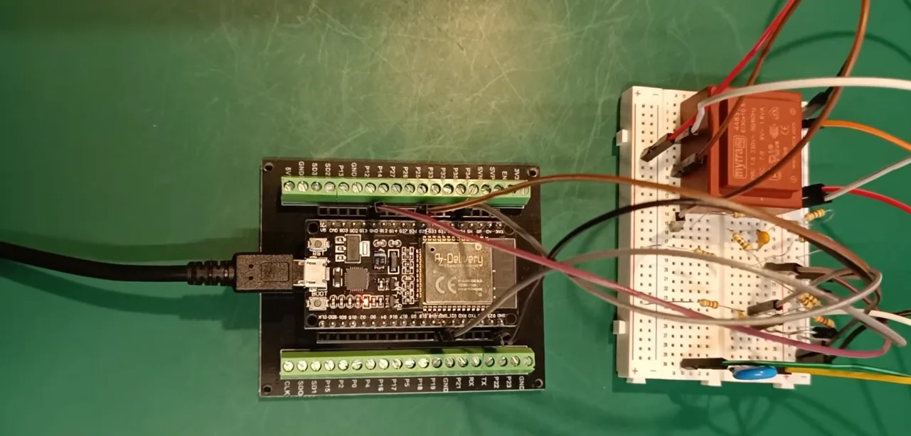
Prototype Mockup
Contents
Overview
The goal of this project is API-first: turn an ESP32 into a small, reliable IoT sensor node that publishes machine-readable RMS measurements and Graph Plot over your local network. The ADC and RMS math are the “sensor backend” — the HTTP JSON endpoint is the product you integrate into tools and dashboards.
This HTTP API is designed for machine consumption (scripts, automation, dashboards), not just manual testing.
What this API enables
- Poll values from scripts and tools (
curl, Python, Go, Bash, CI checks, etc.). - Feed a time-series pipeline (Node-RED → InfluxDB/Prometheus → Grafana).
- Integrate into home/industrial automation (Home Assistant, PLC gateways, custom services).
- Use the ESP32 as a headless measurement endpoint you can deploy anywhere on your LAN.
What this project does
- Provides Wi-Fi provisioning for first-boot setup.
- Samples two analog inputs using ADC1.
- Computes true RMS voltage and Graph Plot over a measurement window.
- Updates results periodically (e.g. every 1–10 seconds).
- Continuously exposes the latest results via a stable HTTP JSON API.
What this project is not
- No continuous raw sample streaming.
- No oscilloscope visualization in Telemetry Viewer.
If you need real-time waveform plotting over USB, use the separate tutorial: Dual ADC + Serial Oscilloscope (Telemetry Viewer).
Architecture at a glance
The firmware is structured so the HTTP server always responds quickly: measurements happen in the background and the API serves the latest completed result from a shared cache.
ADC (CH_A, CH_B)
   ↓  periodic sampling window
RMS compute task
   ↓  update shared state (latest result)
HTTP server
   ↓
GET /api/rms  → JSON for clients (curl / Node-RED / Grafana / apps)
Key design choice: the device does not sample “on request”. Requests simply return the most recent completed RMS window, keeping Wi-Fi responsive and response times consistent.
What you need
- ESP32 DevKitC (ESP32-WROOM-32) or similar ESP32 board.
- Two analog signals (0–3.3 V). See this video tutorial for an example circuit..
- USB cable for flashing and serial logs.
- A phone or laptop to connect to the provisioning portal.
ESP32 ADC inputs must stay within 0–3.3 V. Never exceed 3.3 V on GPIO34/GPIO35.
Wiring (GPIO34 / GPIO35)
This tutorial intentionally uses ADC1 only to avoid ADC2/Wi-Fi conflicts.
| Channel | GPIO | ADC Unit | Notes |
|---|---|---|---|
| CH_A | GPIO34 | ADC1 | Input-only pin (great for ADC) |
| CH_B | GPIO35 | ADC1 | Input-only pin (great for ADC) |
Connect the signal ground to ESP32 GND, otherwise your readings will be unstable and meaningless.
VS Code + ESP-IDF Setup
Install ESP-IDF and the VS Code extension exactly like in the serial oscilloscope tutorial. If you already have ESP-IDF installed, you can skip directly to cloning the project.
- Install Visual Studio Code
- Install the Espressif IDF extension
- Run the ESP-IDF setup wizard (toolchain + Python + IDF)
Use a stable ESP-IDF release and keep it consistent across your projects. This tutorial was developed using Visual Studio Code v1.108.1 and ESP-IDF v1.11.1.
Get the code (GitHub)
The complete firmware for this tutorial is hosted on GitHub: esp32-dual-adc-rms-wifi
Clone it locally:
git clone https://github.com/jak-services/esp32-adc-rms-wifi-api.git
cd esp32-adc-rms-wifi-api
Build the project
This is a standard ESP-IDF project (CMake). Open the folder in VS Code and use the ESP-IDF commands.
- Open VS Code in the project folder.
- Set the target (if needed, CTRL + SHIFT + P) : ESP-IDF: Set Espressif Device Target → esp32.
- Configure your serial port (CTRL + SHIFT + P) : ESP-IDF: Select Port to Use.
- Build/Flash (CTRL + SHIFT + P) : ESP-IDF: Build, Flash and Start a Monitor on Your Device.
Most DevKitC boards auto-enter bootloader. If flashing hangs at “Connecting…”, hold BOOT, click flash, then release BOOT when you see “Writing at …”.
Firmware tour: Boot → Measure → Serve
This project is intentionally split into multiple files so each subsystem stays readable: ADC sampling, RMS processing, provisioning, and the HTTP server.
High-level flow
- Boot: initialize NVS + logging.
- Wi-Fi: connect (or start provisioning if needed).
- Measure: periodically capture samples and compute RMS.
- Serve: return cached results instantly via HTTP.
Pseudo-entrypoint (for orientation)
The main idea is always the same: start Wi-Fi, start measurement, start server.
// PSEUDO-CODE (illustration)

void app_main(void)
{
    nvs_init();
    wifi_init_and_connect_or_provision();

    measurements_init();         // allocate buffers, init ADC config
    measurements_start_task();   // periodic capture + RMS compute

    http_server_start();         // exposes /api/rms
}
Wi-Fi provisioning
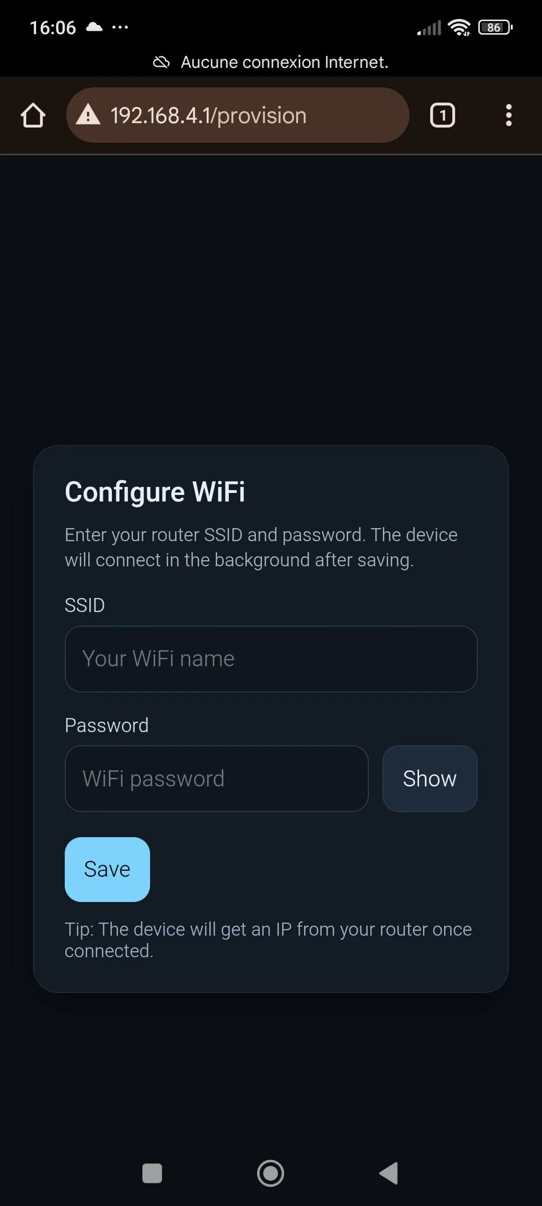
On first boot (or when no Wi-Fi credentials are stored), the device starts a Wi-Fi Access Point and exposes a provisioning portal.
Typical provisioning steps
- Power the ESP32 using a USB cable.
-
On your phone or laptop, open your Wi-Fi settings and connect to the device
access point named
JAK_DEVICE_*, using the passwordconfigureme(this can be changed in theapp_config.hfile). -
If the provisioning page does not open automatically, launch a web browser
and navigate to the device provisioning page using the local IP address
http://192.168.4.1(this can be changed in theapp_config.hfile). - Enter your home Wi-Fi SSID and password.
- The device saves the credentials and connects to your home Wi-Fi network.
Once connected to your home Wi-Fi, the ESP32 is assigned an IP address by your
router. This IP address is printed in the API.
From this point on, you can access the ESP32 from any phone or computer
connected to the same home Wi-Fi network using this IP address, without
needing to connect to the JAK_DEVICE_* access point.
The provisioning access point remains available at all times if you need to
reconfigure the device or switch to a different Wi-Fi network.
Security considerations
The provisioning access point is protected using WPA2 with a configurable
password, preventing unauthorized connections during setup.
All services provided by the device (provisioning interface and HTTP API)
are accessible only from the local network and are not exposed to the
internet. The device does not initiate any external network connections
or rely on cloud services.
The HTTP API does not implement authentication or encryption and is intended
for use in trusted local environments. If stronger security is required
(for example HTTPS, authentication, or restricted access), additional
measures, not included in this tutorial, should be implemented.
HTTP API (JSON)
The API returns the latest completed RMS measurements and Graph Plot. Sampling is not done on-demand, so requests stay fast and Wi-Fi remains responsive.
Endpoint
GET /api/rmsExample response
{
  "channel_a_rms": 1.237,
  "channel_b_rms": 0.982,
  "unit": "volts",
  "timestamp_ms": 12345678
}
Test with curl
Once your device is on Wi-Fi, find its IP address in the API (or serial logs), then:
curl http://<ESP32_IP>/api/rmsIf you plan to integrate with dashboards (Home Assistant, Node-RED, Grafana, etc.), keep the JSON stable and version your API when you introduce breaking changes.
Build, Flash, Monitor, Debug
Build + Flash
- Run (CTRL + SHIFT + P): ESP-IDF: Full Clean Project.
- Run (CTRL + SHIFT + P): ESP-IDF: Build, Flash and Start a Monitor on Your Device.
Serial monitor
Use (CTRL + SHIFT + P) ESP-IDF: Monitor to confirm:
- Provisioning mode starts (first boot) OR Wi-Fi connects (already provisioned)
- IP address is printed
- Measurement loop runs (periodic “RMS updated” logs, if enabled)
- HTTP server is listening
Only one program can open the serial port at a time. Close the monitor (CTRL + T then CTRL + X) if another tool needs the COM port.
Troubleshooting
Unstable readings / noise
- Make sure signal ground is connected to ESP32 GND.
- Use short wires and avoid breadboard mess for low-level signals.
- Consider averaging, filtering, and calibration (especially for precise voltage numbers).
Can’t access the API after provisioning
- During initial setup, connect to the provisioning access point named JAK_DEVICE_* to enter your home Wi-Fi SSID and password.
- After credentials are saved, disconnect from JAK_DEVICE_* and reconnect your client device to your home router’s Wi-Fi network.
- The RMS HTTP API is accessible only when both the ESP32 and your client are on the same home network.
- Use the router-assigned IP address shown in the serial logs to access the API.
Wi-Fi connects but API does not respond
- Confirm the IP address in the serial logs.
- Try
http://<ip>/api/rmsin a browser. - Check that your firewall/network isolation is not blocking local traffic.
- If using a phone, disable Wi-Fi roaming / Wi-Fi Assist / mobile data switching. Some phones automatically switch to cellular or another access point, which prevents access to local network devices.
Why ADC1 only?
On ESP32, ADC2 is shared with Wi-Fi. Using ADC2 while Wi-Fi is active can produce invalid readings or failures. This project uses ADC1 only for robust operation.
Resources
- Espressif documentation: documentation.espressif.com
- ESP-IDF programming guide: ESP-IDF (esp32)
- Visual Studio Code: Visual Studio Code Download